Off-CarPractical 3
CTS (Coolant Temperature Sensor)
THw (Thermistor water)
ECT (Engine Coolant Temperature)

To test the sensor we heat up the water in the container than we check change in the thermostor, as the temperature increases the sensor resistance decrease.

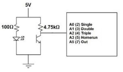
This picture show the two terminal used to measure the resistance.
Water Temperature Sensor (THW)
WATER TEMPERATURE (In degree) | RESISTANCE |
25c | 1.81k |
35c | 1.57k |
45c | 1k |
50c | 0.87k |
55c | 0.71k |
60c | 0.65k |
65c | 60k |
Specification
Engine Cold 1500 – 3500ohms
Engine Hot 200 – 400ohms
Engine Hot 200 – 400ohms

Engine Electronic Control Systems
Does the sensor meet the manufacturer’s specifications why or why not?
Yes, the spec and the graph above shows exact acceptable relation of the resistance and the temperature when is cold until it gets hot.
What type of thermistor is this?
Water Temperature Sensor
Explain the internal operation of the sensor?
The test starts at the room temperature of 25 degrees and the ohm-meter of about 1.8kilo-ohms. Now this thermistor has a negative temperature coefficient unfortunately the room temperature is the starting point in this case. Once the water is heat up the resistance value decreases and as coolant temperature rises as you can see in the graph above demonstrates the relationship.
Thermo Fan Switch
Suspend the engine thermo fan switch in a container of water as shown to heat the sensor. As the water heat up the water temperature change.Engine Electronic Control Systems
Temperature (In Degrees) | Resistance |
| 100c | 9.0ohms |
| 90c | 8.0ohms |
| 80c | 7.0ohms |
| 70c | 6.0ohms |
| 60c | 5.0ohms |
| 50c | 4.0ohms |
| 40c | 3.0ohms |
| 30c | 2.0oms |
| 20c | 1.0ohms |
| 10c | 0.0ohms |
Graph

The Fan switch does meet the specifications as it switches at the correct temperature of about 85-90degrees. This activates the fan and start to cool the coolant.
Is this a thermistor?
Is this a thermistor?
Yes
Explain the internal operation and why your resistance changes?
When the thermistor is cold, the resistance of the sensor is high, and so the voltage. As the sensor warms up, the resistance drops and voltage signal decreases.
As the temperature of the sensor heats up, the voltage signal decreases. This signal is caused by the decrease in resistance. The change in resistance causes the voltage signal to drop.
ATS (Air Temperature Sensor)
THA (Thermistor Air)
IAT (Intake Air Temperature)
Specification
Intake Air Temp (Degrees) | Resistance |
20c | 2000 – 3000 ohms |
80c | 200 – 300 ohms |
Note the resistance change.
TEMPERATURE (In degree) | RESISTANCE |
100c | 489.0 ohms |
90c | 899.9 ohms |
80c | 0.190k |
70c | 0.575k |
60c | 0.774k |
50c | 1.081k |
40c | 1.460k |
30c | 2.336k |
20c | 2.888k |
Measure the Resistance between the two terminals

Operation
This is an air temperature sensor and purpose is to help ECU to determine the air density as the higher the temperature the lower the resistance in the sensor. Simply stated the higher the air temperature gets the less dense the air becoming. As the air becomes less dense the ECU monitoring the fuel flow. If the fuel flow was not changed the engine would become rich possible losing power and consuming more fuel. The temperature sensor is located in the air inlet tube or the air box.
Knock sensor
Waveform of the Knock sensor

B - Strong signal creates AC voltage
C - Weak signal
Operation
To test the sensor the signal appear when sudden knock occur to the sensor, this generate voltage whenever it is exposed to vibration. When the engine detonated occur vibration of the cylinder signal varies in amplitude depend on the intensity of knocks. Big knock can create high vibration causing strong signal relate to the voltages. If the knock is weak the voltage would not create.
Oxygen Sensor

B - Lean mixture
C - Average voltage normally a perfect position for O2 Sensor.
Operation
When exhaust oxygen content is high, oxygen sensor voltage output is low. When exhaust oxygen content is low, oxygen sensor voltage output is high. The greater the difference in oxygen content between the exhaust stream and atmosphere, the higher the voltage signal.
Speed or Position Sensors
Inductive sensor Magnetic reluctor sensorSpecification | Actual | Serviceable? | |
G Pick up coil | Air Gap:0.2-0.4mm (0.008-0.016 in) | 3.0mm | Yes |
NE Pick up coil | Air Gap:0.2-0.4mm | `3.10mm | Yes |

Analogue signal

Operation
The sensor uses a magnetic pickup to produce a signal. A small magnet is attached to the one end, and this assembly is mounted in the distributor facing the distributor shaft. When a notch, pin, teeth or hole in a timing wheel reluctor moves past the sensor causes a change in the magnetic flux field around the sensor. As the teeth of the reluctor approach the coil assembly, the flux from the magnet is pulled in close to the bar. The sudden field change induces an electrical current in the coil, which is then converted to a voltage signal by electronic circuitry in Mega Squirt-II. As the teeth move away, the flux springs back outward, inducing a voltage in the pickup coil. This induced current has reversed direction as the magnetic field returns to normal.
Hall -Effect Sensors (Distributor)
Degrees turned | Voltage |
60 | 2.00 |
120 | 3.1 |
180 | 2.00 |
240 | 3.1 |
330 | 2.00 |
360 | 3.1 |
Digital Signal

A - Dwell period. the Coil is Charge up.
B - Firing Voltage. the firing voltage period
C - 3 Volts signal ON and OFF. This pull the signal voltage to ground.

Operation
The operation for this sensor is when the voltage is applied across the end of a special crystal, a small current voltage will appear across the edges of that crystal when a magnet is held perpendicularly to the face of the conductor. Operation
Optical (Distributor)
 Operation

Optical Distributor fitted with an optical pickup assembly with light-emitter diode (LED) and photo diode. A thine plate attached to the distributor shaft rotates between the LED above the plate wire up the distributor as sand photo diode below the plate. This plate certainest six equally speed slots that rotate directly below the LED and photo diode.
The inner LED and photo diode act as reference pickup. As in Hall Effect pickup system terms the reference pickup in the optical distributor provides a crankshaft position and speed signal to the PCM. When the ignition switch is on . The PCM supply voltage to the optical pickup that cause the LED to emit light. If solid part of the plate is under reference LED, this light does not shine on the photo diode. Under this condition the photo diode does not conduct current and the reference slot move under LED, the light shine on the photo diode and this diode conduct current and the reference voltage signal to PCM is 5v.
Red -12V
Black- Earth
Blue –signal out
Position | Voltage |
60 | 12v |
120 | 12v |
180 | 12v |
240 | 12v |
300 | 12v |
360 | 12v |
The waveform

A -Dwell Time
B -Earth Trigger
C -Firing Voltage
Explain the difference between Hall Effect, optical and inductive signals
Hall Effect and Induction are non contact system but different in measures.
They both operate in different technology.
In each of the speed sensors above, how does the degrees turned relate to the degrees of crank shaft rotation?
A chip of semi conductor material on Hall Effect carrying a signal current it is exposed to a magnetic field. A small voltage called the hall voltage is generated between the chip edge at 90 degrees to the path take by the signal current. The optical is 360 degree.
No comments:
Post a Comment