ON-Vehicle Input Sensors and Actuators
Make Toyota Model 4A-FE Year 1997
Locate a fuel injector
Record the voltage to the fuel injector 14.04
Discuss why would we bother checking the voltage supply to the fuel injectors?
Here is ensuring the injectors are operate or working probably at their receiving voltages, also check for any poor earth or connection could affect ECU by sent wrong information.
If we find lower voltage at the injectors than at the battery, what can that mean? And how would injector operation be affected?
In terms of lower voltage in the fuel injector, this cause lower percentage at the duty cycle affecting the operation due to weak spark cause engine rich, misfire.
Circuit diagram for the fuel injectors, battery, ignition switch, main relay and injectors switch.

The Circuit Diagram of the Ignition system is switch off show above as an open circuit.
TPS(Throttle Position Sensor)
TPS(Throttle Position Sensor)
Reference Voltage at TPS sensor

TPS sensor mounted on the throttle body
What is the purpose of the reference voltage to the throttle position sensor?
Power up the TPS and for the ECU to determine the position of the throttle. (voltage divider) ECU used this to compare how much air the engine need for sorting time.
What could cause problems so that there is not the correct reference voltage at the throttle position sensor?
Corrosion and bad connection build up a resistance in the circuits affect the supply voltage.
Ground at TPS sensor
Record the voltage on the meter: 25.4mV (A good ground will usually read less than 0.05V. Some manufacturers say 0.10V.)
What does this voltage tell you about the ECU earth or ground? Why is it important to measure it?
This is a good ground for the ECU. Checking ground is important because of completing circuits, most of electronic are earth trigger also note all sensors share a common ground.
Discuss what could go wrong so that the ECU earth or ground is not good:
The ECU will not detect TPS condition than sent fault information by increasing the voltage to other part of the engine. This would affect the engine’s operation causes hard starting, engine runs rough and sending fault reference to other sensor.
Throttle Position Sensor return/output:
Potential-meter Type
Ignition ON: 0.654volts
Half Open Throttle: 1.782volts
Fully open throttle: 3.937volts
Close throttle: 2.101volts
Slowly open the throttle from the closed position to the full open position, and watch that the meter readings slowly increase with no sudden jumps or gaps in the signal.
(OK)
Operation of a TPS
At idle the voltage is approximately 0.6volts on the output signal. From this voltage, the ECU knows the throttle plate is closed. At wide open throttle, the signal voltage is approximately around 3.5volts. Inside the TPS is an resistor and a wiper arm. The arm is always contacting the resistor. At the point of contact, the available voltage is the signal voltage and this indicates throttle valve position. At idle, the resistance between the VC or VCC terminal and VTA terminal is high, therefore, the available voltage is approximately 0.6volts. as the contact arm moves closer the VC terminal(5v power volts), resistance decreases and the voltage signal increases.(signal output voltage to ECU)
Discuss what type of sensor voltages should go to the ECU as the throttle is opened and closed:
Linear Throttle Position Sensor
Describe problems which could occur to prevent the TPS from sending the correct voltage to the ECU:
Corrosion occurs into plug and bad earth would affect the signal.
TPS Circuit Diagram

Throttle Position Switches:
wire: Colour black Volts at Idle 0.07v Volts at part throttle or open throttle 10.79v Wide Open Throttle wire: Colour: black Volts at idle or part throttle: 10.00v Volts at open throttle 0.01v
By watching the voltages above, figure out the circuit diagram for this TPS, and draw it in the box below.
TPS Switch Type

Why is this output needed for the ECU to properly run the engine? How do these outputs change how the engine runs in the different conditions of idle, part throttle cruise, and wide open throttle power?
The output is the signal voltage provided information frequently used in the engine management system indicating the position or condition of the idle and how much air is needed depend on the situation. These change is monitor by the ECU than appropriate adjustments will made required depend weather is accelerate or decelerate.
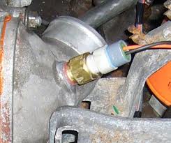
ECT(Engine Coolant Temperature) Sensor

The sensor located in a coolant passage just before the thermostat.
Ignition ON - 1.027v Engine’s Condition: Warming up. Does the voltage reading above seem right for the temperature of the engine: Yes Engine Idle (Warm) 0.8v Is the reading above lower than the first reading? Yes
Describe how an ECT sensor works.
This is resistive sensor in the cooling system. As the temperature of the water changes, so the resistance change. The changes in resistance are monitored by the ECU and appropriate adjustment is made when required to the air and fuel mixture.
When the temperature is cold the (ECT) sensor resistance is increase. As the temperature rises the resistance decrease. The changes cause the signal volts output to the ECU.
Describe how the ECT sensor voltage affects the fuel injection output from the ECU.
When the ignition key On, the feedback from the engine coolant temperature sensor will first inform the ECU of what type of engine start is required weather is cold or warm. In cold start the ECT signal the ECU to provide more fuel efficient affecting the fuel injectors to open longer so that more fuel can draw on the cylinders.
Describe what could go wrong to create an incorrect voltage for the ECU:
High resistance in connections could causes by corrosion from coolant, water, salt air and engine vibration and thermal stress cause lose connections.
Ground Coolant Temperature Sensor
Record the voltage on the meter: 7.7mV (A good ground will usually read less than 0.05V. Some manufacturers say 0.10V.)
What does this voltage tell you about the ECU earth or ground? Why is it important to measure it?
This is a good ground for the ECU. Checking ground is important because of completing circuits, most of electronic are earth trigger also note all sensors share a common ground. All the sensors affect if a problem occurs in the circuits.
Discuss what could go wrong so that the ECU earth or ground is not good:
Engine runs rough. Hard to start sensors values will be higher than normal cause by bad earth.
ECT and ECU circuit diagram

RPM Sensor or Crank Position Sensor (CKP):

This sensor is mounted close to a toothed gear or located inside the distributor.
Start the engine. 0.5mV. RPM Increase to 2500 rpm: 5.24v Return the engine to idle speed: -164.9mV. Increase engine RPM to 2500 rpm. -282.6mV Return the engine to idle speed.
Record the reading from the meter 0.402k Hz. Increase engine RPM to about 2500 rpm. 1455Hz. Return the engine to idle speed, and shut off the engine. AC voltage
Type
Inductive type
RPM Operation
The ECU uses crankshaft position signal to determine engine RPM. This signal is referred to as the NE signal. The NE signal combined with the G signal indicates the cylinder that is on compression and the ECU can determine from its programming the engine firing order.

Discuss how using different functions of your meter can help you to accurately measure the sensor output when you don’t have an oscilloscope available?

Discuss how using different functions of your meter can help you to accurately measure the sensor output when you don’t have an oscilloscope available?
The voltage test explains the ECU signal and shows the condition of the engine as RPM change. The change on RPM detect if the voltage is acceptable. In Hz this indicates the engines speed.
What can go wrong so the ECU did not receive the correct signal from the RPM or Crank sensor:
Poor ground cause fail on fuel injection like misfires and fault occurs on the MAP
RPM Circuit Diagram

MAP or MAF Sensor:
MAPSensor (Manifold Absolute Pressure)

The MAP is located either directly on the intake manifold or it is mounted high in the engine apartment and connected to the intake manifold with vacuum hose.

The MAP is located either directly on the intake manifold or it is mounted high in the engine apartment and connected to the intake manifold with vacuum hose.
MAP Sensor Test
Set up the voltmeter to read DC volts 3.624v

Ignition ON: 3.619v

engine idle: 1.401volts

Increase short acceleration: 3.568v
MAP Sensor Operation
MAP Sensor Operation
Intake manifold pressure is a directly related to engine load. The ECU needs to know intake manifold pressure to calculate how much fuel to inject, when to ignite the cylinder. The sensor uses a silicon chip with a calibrated reference pressure. Changes in vapour pressure cause the chip to flex and vary the voltage signal to the ECU. The voltage signal out depends on the difference between atmospheric pressure and vapour pressure as vapour pressure increases the voltage signal increases.
Discuss how the readings above are correct or incorrect for this engine:
When the ignition turn ON, the volts reading represent atmospheric pressure with the throttle closed. At the engine idle (part throttle) the vacuum pressure causing decrease in voltage. With a quit short acceleration, here at wide open throttle again drawn atmospheric pressure, the vacuum become rich and useless. This increases the voltage back as when the ignition ON. Now we think the vacuum work perfectly.
What could go wrong so the ECU did not receive the correct signal from the MAP sensor?
Air leaks in the induction manifold will lead to poor engine performance and erratic idling. The ECU would fail to perform by incorrect voltage.
MAP Circuit Diagram

MAFsensor:
(Hot wire type)


The MAF sensor is located directly in the intake air stream, between the air cleaner and throttle body where it can measure incoming air.
Yellow
1 Temperature Switch (E2G)
1 Temperature Switch (E2G)
2 Battery volts (+B terminals supplies volts)
3 Earth (E2 ground)
4 Ref volts (THA 5volts)
5 signal voltage VG signal line)

Hz: 0.00Hz Ignition ON: 0.00Hz Engine Idle: 0.00Hz
Short acceleration: 0.185Hz

The picture shows MAF's frequency's at engine idle
Describe how the MAF sensor works to tell the ECU how much air came into the engine. Include what readings might be normal under different load conditions.
The mass air flow sensors convert the amount of air drawn into the engine into a voltage signal.
The primary components of the MAF sensor are a thermistor, a platinum hot wire, and an electronic control circuit. The thermistor measures the temperature of the incoming air. The hot wire is maintained at a constant temperature in relation to the thermistor by the electronic control circuit. an increase in air flow will cause the hot wire to lose heat faster and the electronic control circuitry will compensate by sending more current through the wire. The circuit simultaneously measures the current flow and puts out a voltage signal (VG) in proportion to current flow.
Waveform

Discuss how the MAF readings above are correct or incorrect for this engine:
This test record and compare result due to specification so the reading match the operation.
What could go wrong so the ECU did not receive the correct signal from the MAF sensor?
Bad earth cause by unexpected resistance occur on the connecting wire.
MAF Circuit Diagram

IATSensor (Intake Air Temperature)

IATSensor (Intake Air Temperature)
The IAT sensor located in an intake air passage
Is the reading more or less than the reading you had for the ECT?
More
Does this show the IAT sensor is colder or hotter than the ECT sensor?
Hotter
Describe how the IAT sensor works.
The IAT is used for detecting ambient temperature on a cold start and intake air temperature as the engine heats up the incoming air. As the temperature of the sensor heats up, the voltage signal decreases. The decrease in the voltage signal is caused by the decrease in resistance. The change in resistance causes the voltage signal to drop.
Describe how the IAT reading affects the ECU outputs for fuel injection. Include how an incorrect input could affect the fuel injection and engine running:
The ECU used the Air Temperature along with Cooling Temperature sensors to help determine the proper amount of fuel and how long to open the fuel injectors. It also used this data to determine how much the ignition timing should be advanced as well as the proper setting for the ISC to maintain the proper idle speed. When air temperature is lower the respective thermistors resistance increases and the ECU receive a high voltage signal at the sensor wire.
One strategy the ECU uses to determine a cold engine start is by comparing the ECT and IAT signal. If both are within 8’c (15’F) of each other, the ECU assumes it is a cold start, this strategy is important because some diagnostic monitors, such as the EVAP monitor, are on a cold start.
Describe how the IAT sensor signal should change for different air temperature conditions;
When the sensor is cold, the resistance of the sensor is high, and the voltage signal is high, and the voltage signal is high. As the sensor warms up, the resistance drops and voltage signal decreases. For the voltage signal, the ECU can determine the temperature of the coolant and intake air.
Describe what could go wrong to create an incorrect IAT signal for the ECU:
Resistance in the circuits cause high voltage or short wire due to bad earth affect the signal.
Intake Air Temperature Sensor Circuit Diagram
Intake Air Temperature Sensor Circuit Diagram

CMP(Camshaft Position Sensor)

DC Volts: 4.9v
AC Volts:0.35
HZ (hertz): 0.55Hz
% Duty Cycle 68%
Duty Cycle and Hz as recorded indicate the best measurement to determine the engines cycle when operate due to speeds.
Cam Position Sensor Circuit Diagram

No comments:
Post a Comment